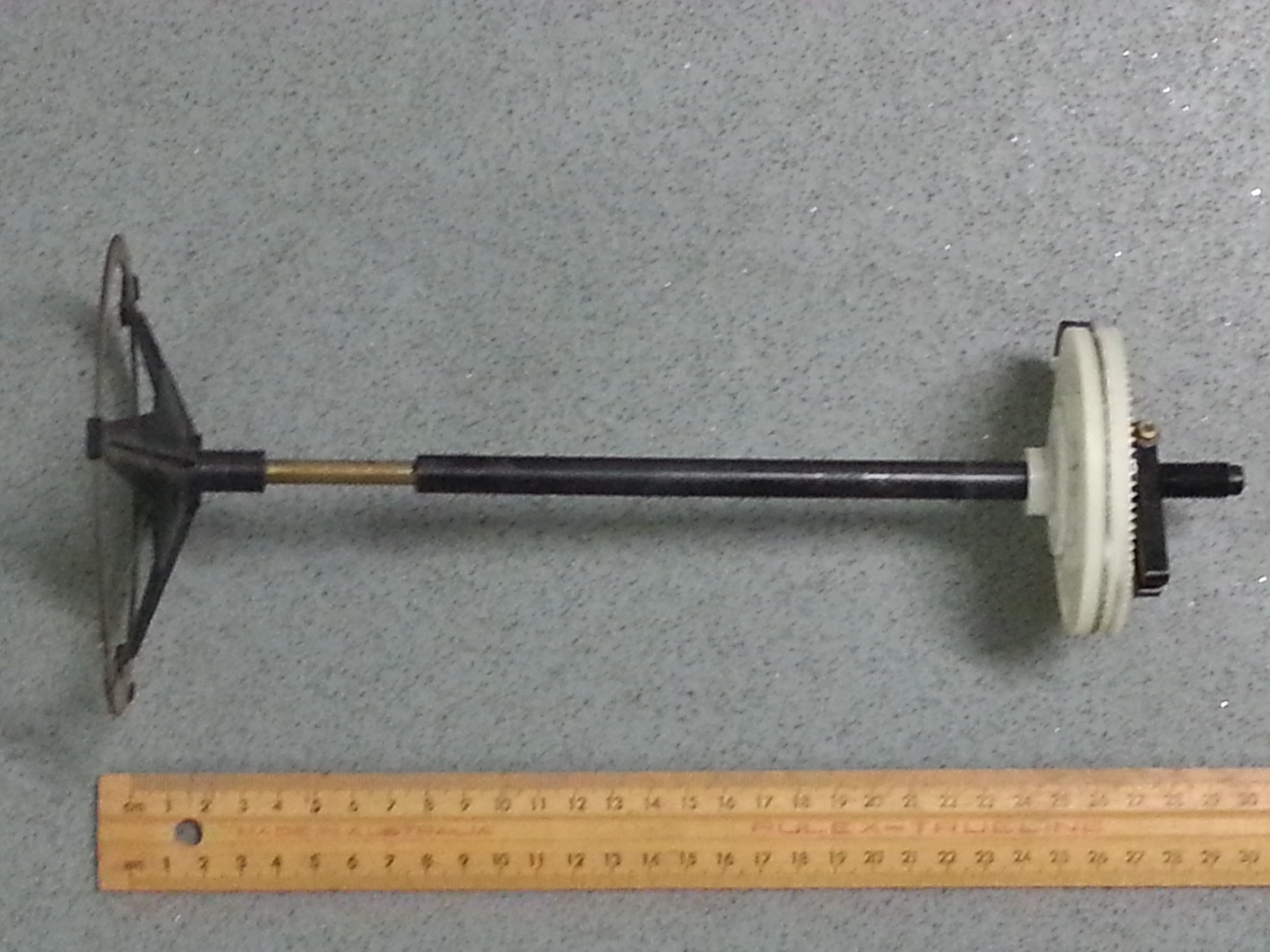
A ring antenna – end on view. 22 or 21 antennae make up a module — about 4.4 meters along the telescope going East-West.
Ring antenna – side view. The brass section at left is a quarter wavelength “stub” which feeds a resonance chamber. There are either 22 or 21 feeds from ring antennae into each chamber.A set of ring antenna cogs.
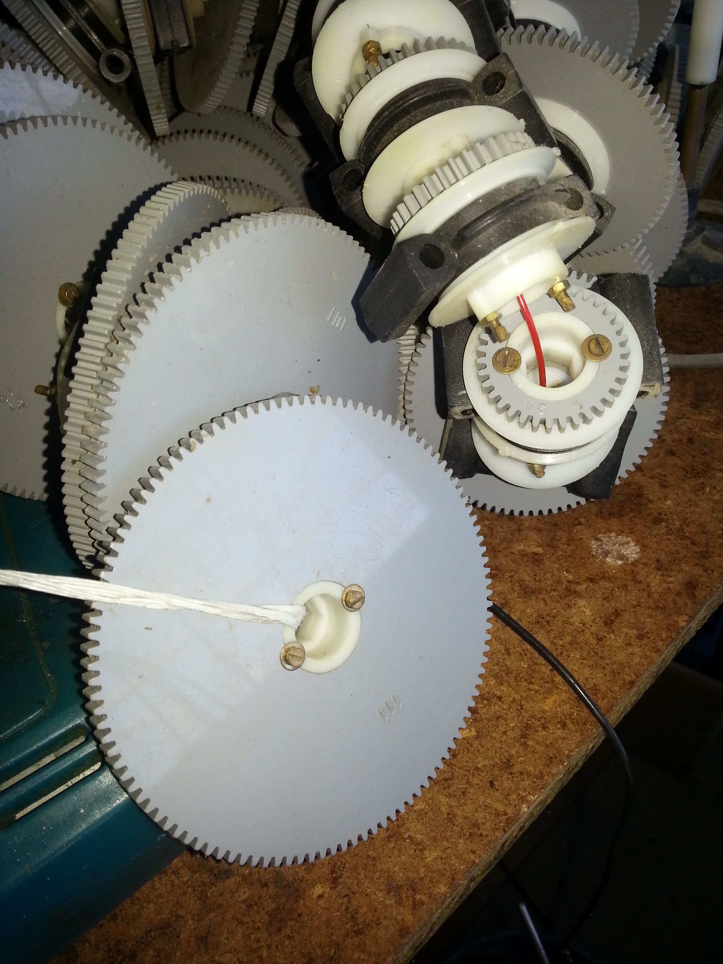
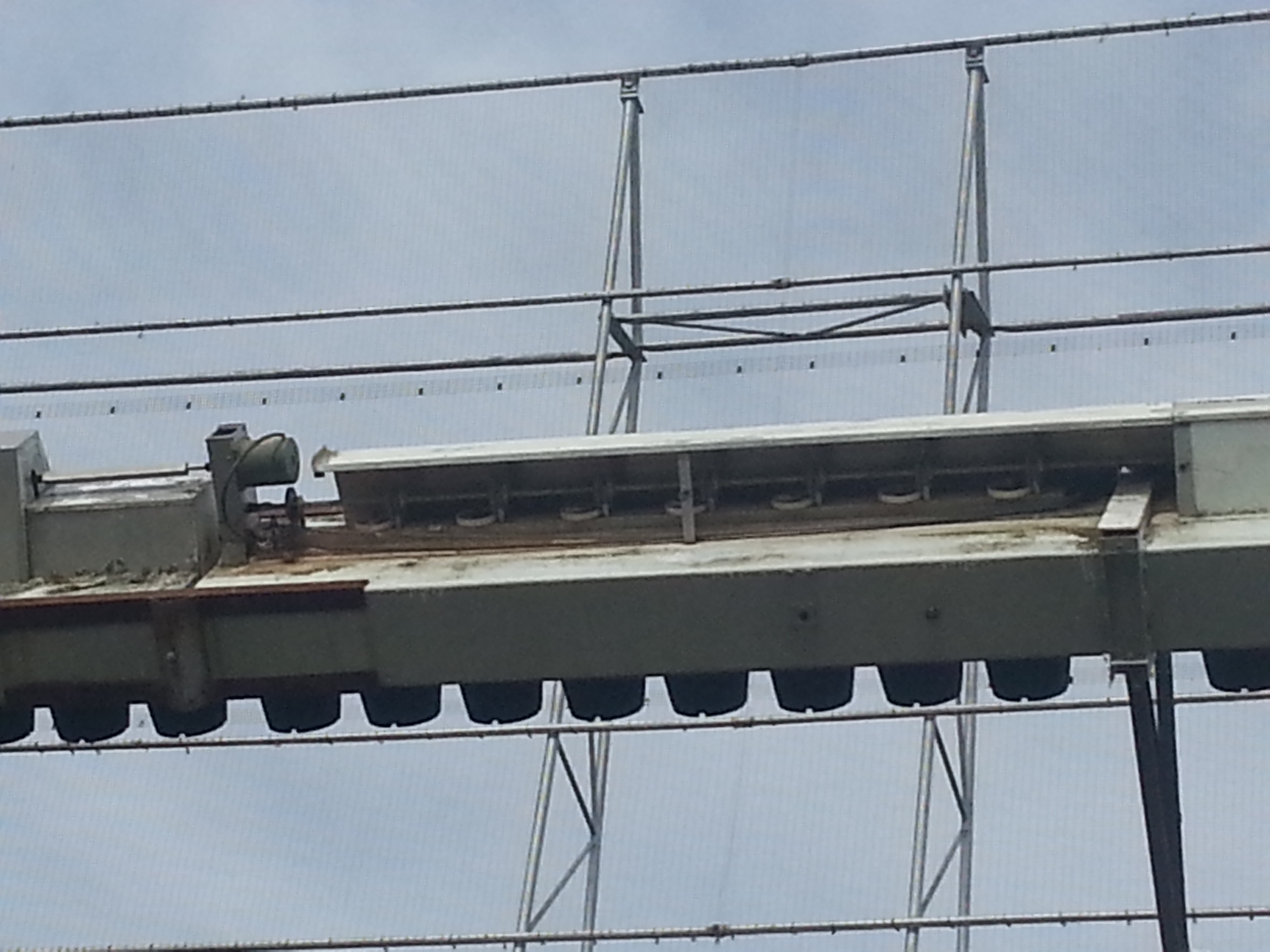
Meridian drive — the vertical gears have one less tooth for each ring antenna: their rotation rates vary with distance along the bay.
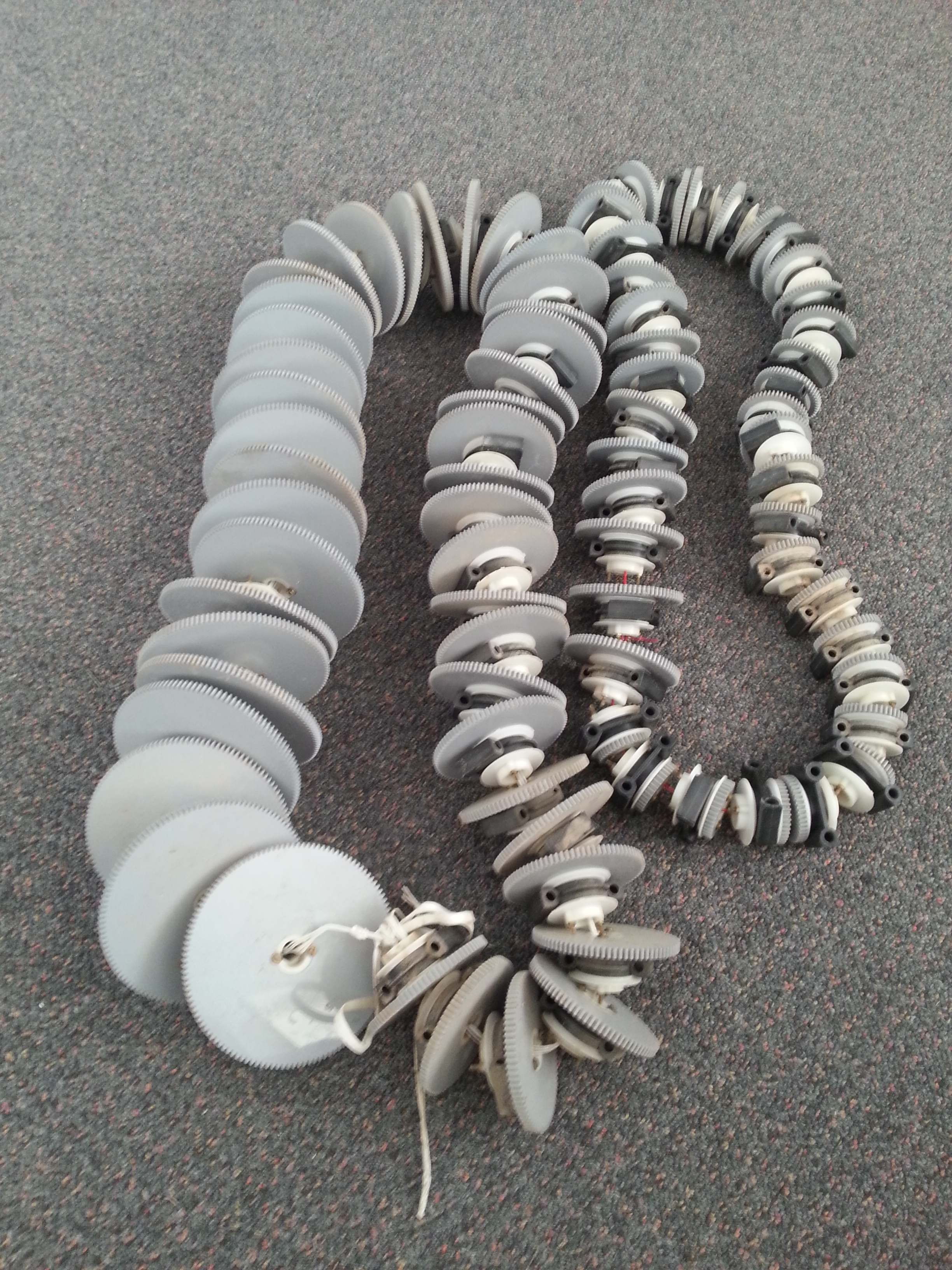
Some of a set of 86 cogs used to rotate the ring antennae at appropriate rates. The large cog has 111 teeth (the maximum is 124). The small cog has 34 teeth (and is the smallest cog in the chain). Note that there are a few missing cogs where the structure needs to be supported, and there is no ring antenna or cog at these locations.
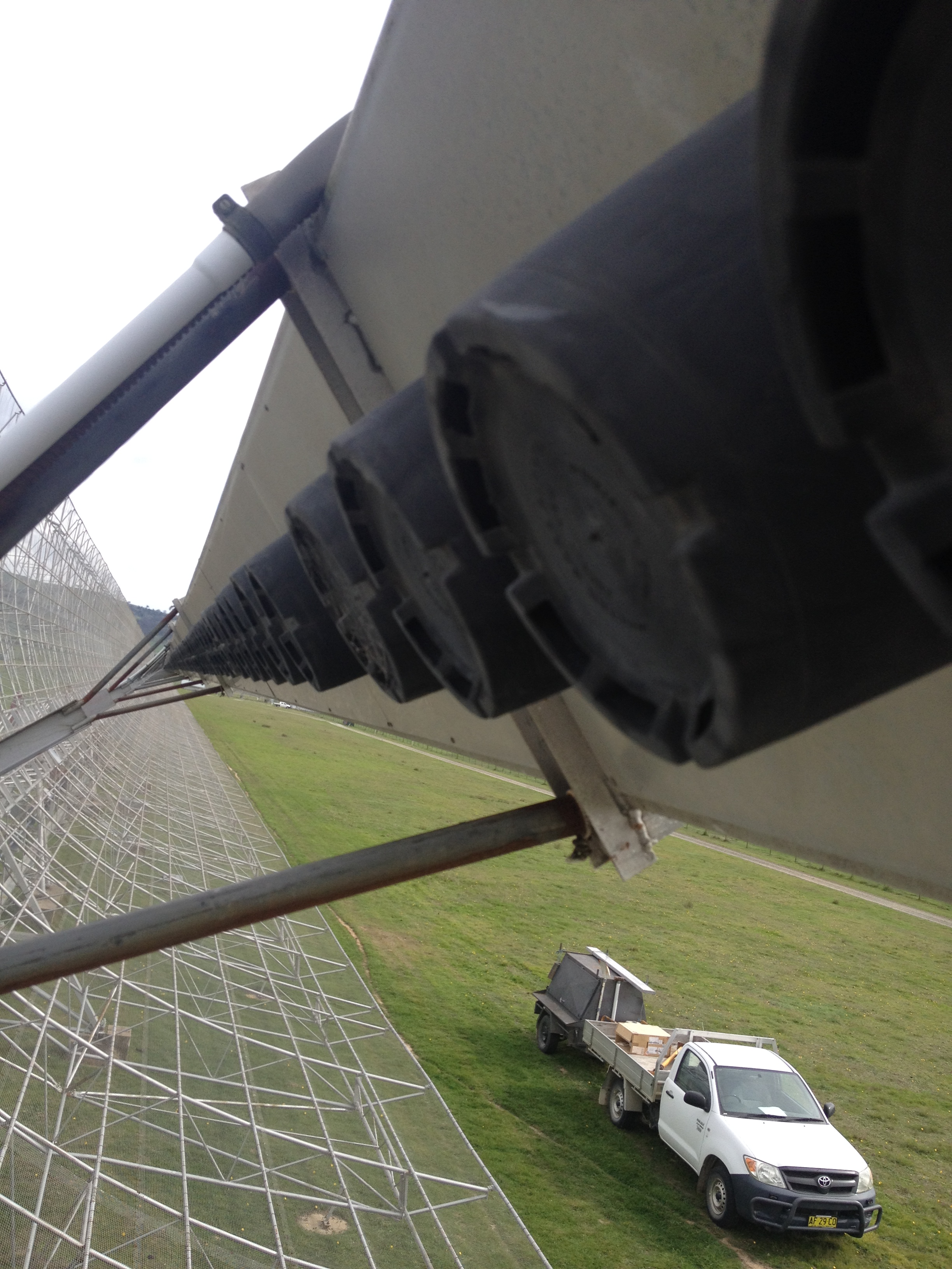
Flower-pot covers for the ring antennae, spaced half a wavelength apart.
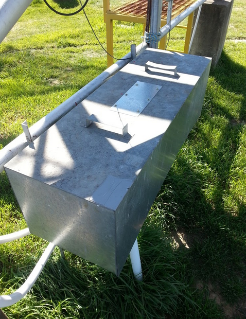
View of the meridian drive system with ring antennae geared with a linearly varying ratio with distance. The meridian motor is seen top left with a square axle (to its left). This feeds a gear box (far left) which turns the axle running from left to right with 7 vertical cogs driving the top gear on the ring antennae.44 RX receivers along each arm are weather protected by sheet metal boxes.
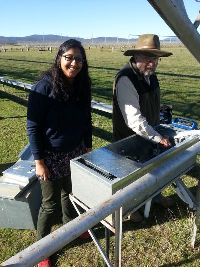
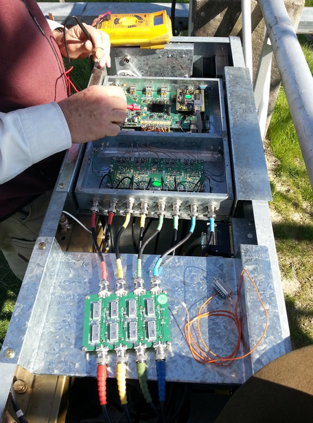
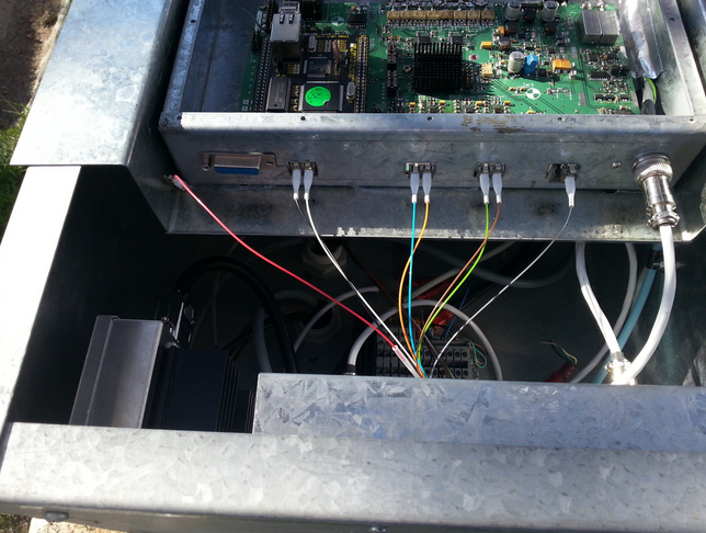
Shivani and Duncan installing one of 88 RX boxes.An RX box being tested in the field. Filter set in foreground with RF feeds from the LNAs from four modules of the bay.An RX box being tested in the field. Filter set in foreground with RF feeds from the LNAs from four modules of the bay.
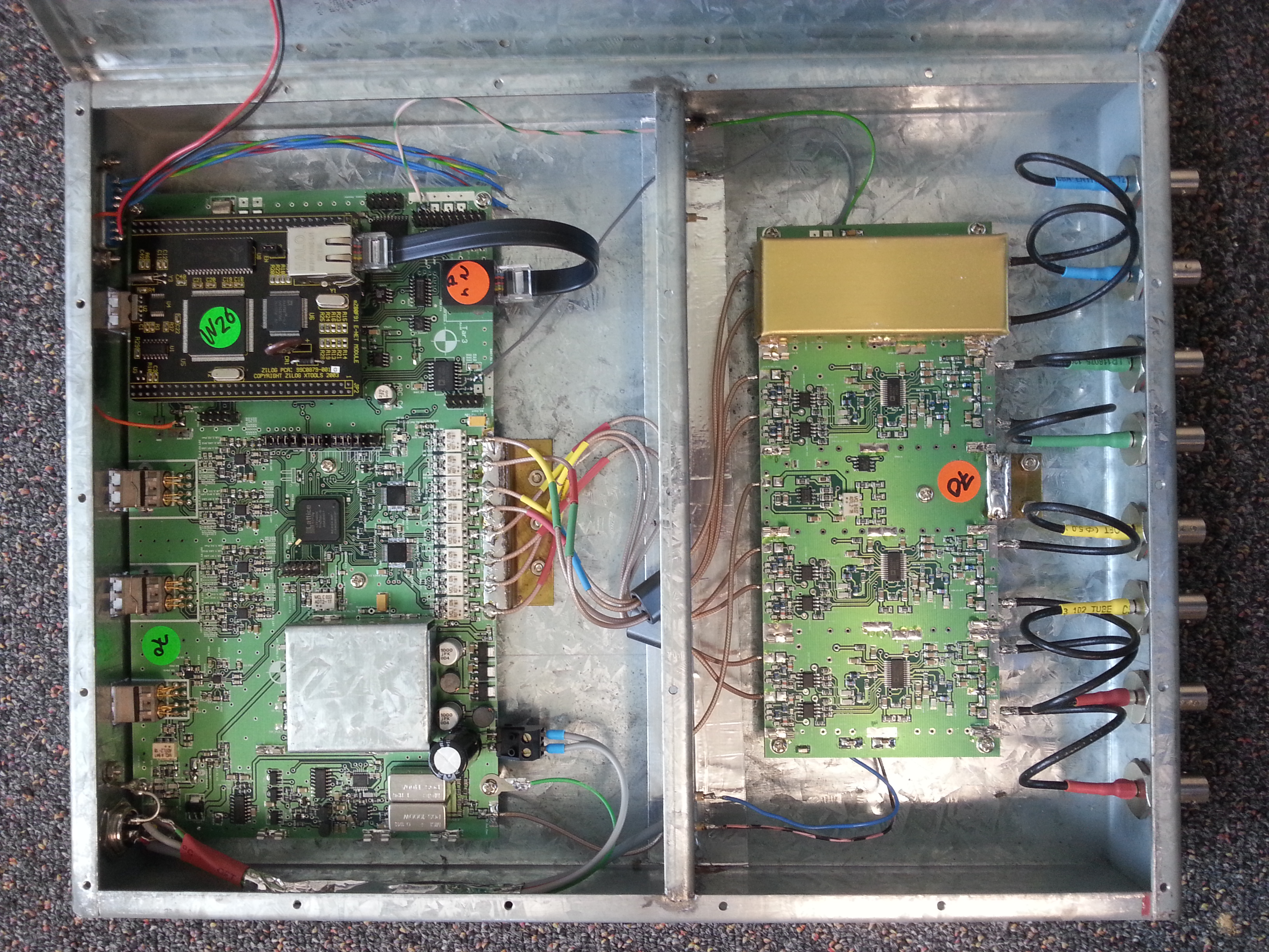
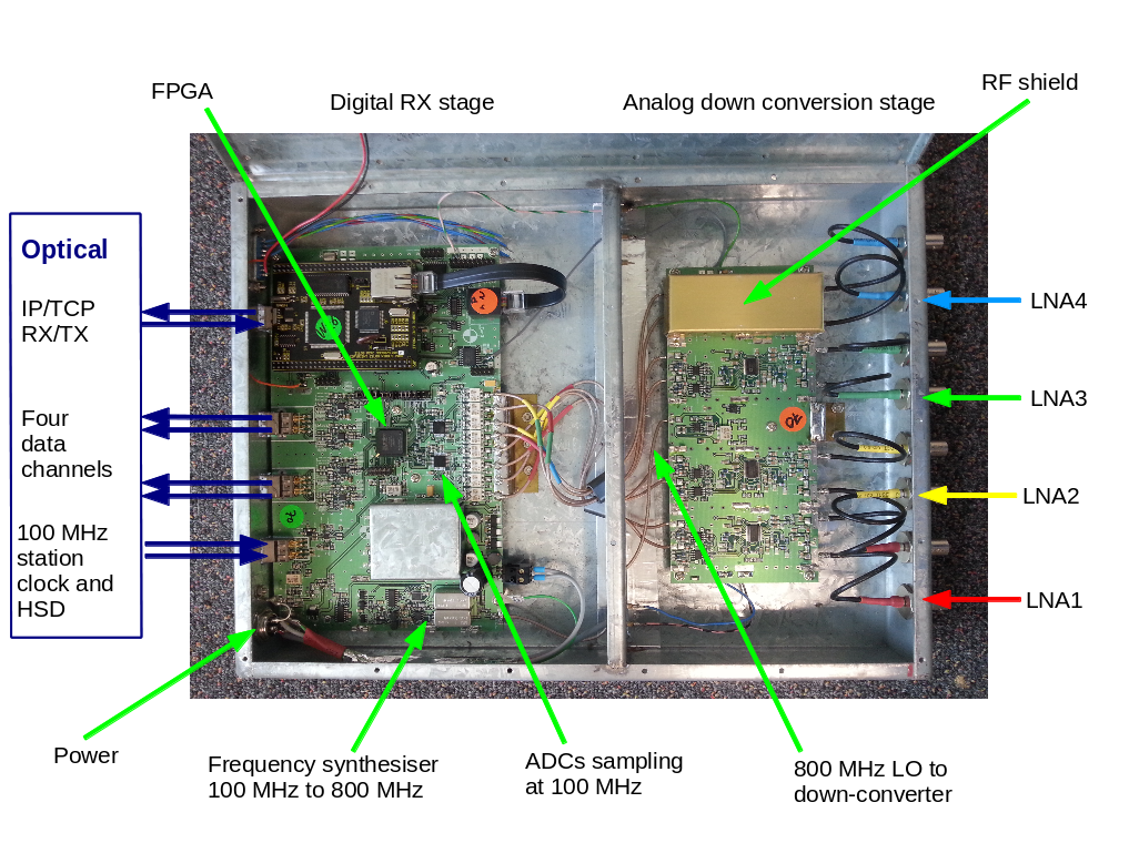
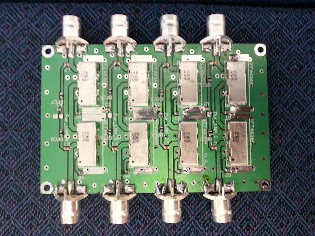
RX card prior to wiring up and microcontroller insertion. LO/HD fibres come out top left; middle 4 optical outputs are for data, and the rightmost optical connector is for IP RX/TX.Custom design filter board for removing the carrier frequency of the nearest Telstra tower.
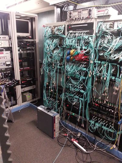
View of the “Burst Room”, with telescope control hardware left and the optical fibre patchboards and transfer to PFBs on the right.
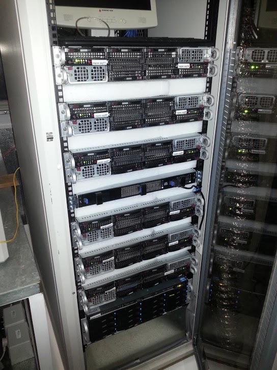
The Swinburne/Molonglo GPU-based supercomputer — 11 slices host 22 GPUs.
UTMOST’s new GPU install took place on May 26th 2015. Eight 4xGPU NVIDIA TitanX servers have just been installed into the right hand rack pictured below, next to our set of 11 of 2xGPU NVIDIA GTX690s (installed in June 2013, and in the left hand rack). The new units were fully operation by the end of the week of the install, with correlation and pulsar observing possible using every element of the array. The system can peak to 258 TFlops of processing power. Observing with UTMOST presently produces 22 GBytes of data per second.