|
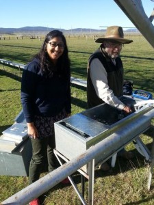
Molonglo consists of 352 modules — individually phased antennae — with dimensions of 4.4 x 11.6 metres. The 352 modules of the telescope feed into 88 receiver boxes, deployed in the field under the array, each fed from 4 LNAs in the telescope top-end, and returning 100 MHz baseband over optical fibre to a central building, stationed just North of the center of the East and West arms. The image shows Duncan Campbell-Wilson and Shivani Bhandari working on one of the receiver boxes in the field. Each has several layers of weather shielding and extraction fans to remove heat from the enclosure.
|
|
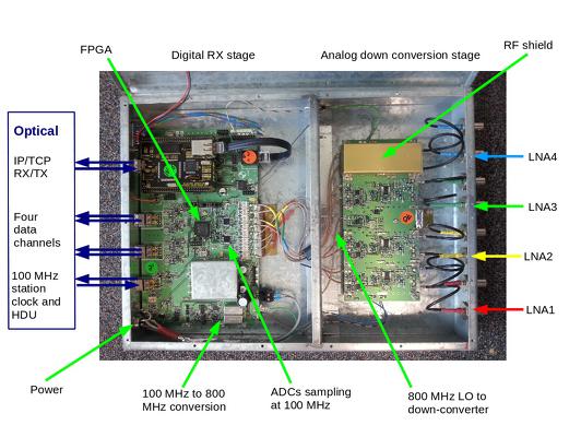
The receivers were developed by Sydney University and CSIRO as part of the SKAMP2 project. The consist of a 800 MHz downconversion stage, which is fed by the 4 LNAs (wired up with colours of red, yellow, green and blue in the field). The 800 MHz local oscillator signal is generated from a 100 MHz station clock, common to all RX boxes, and taken out to the field on optical fibre. After the down conversion, the four signals are digitized at 100 MHz using two quad-feed ADCs, and fed to an FPGA, and then to four laser diodes, which convert the electrical signal to optical. These four data streams are sent back to the central building at Molonglo (to the “Burst Room”). The data rate is 22 Gbytes/sec, as only about 30 MHz of the 100 MHz needs to be transmitted. A microprocessor card (EZ80), connected by IP/TCP over fibre, can be seen in the top left of the figure. This is used to upload the FPGA software when the boxes boot up, and control the RX operations.
|
|
|
Schematic diagram of the full system from antennae to end user
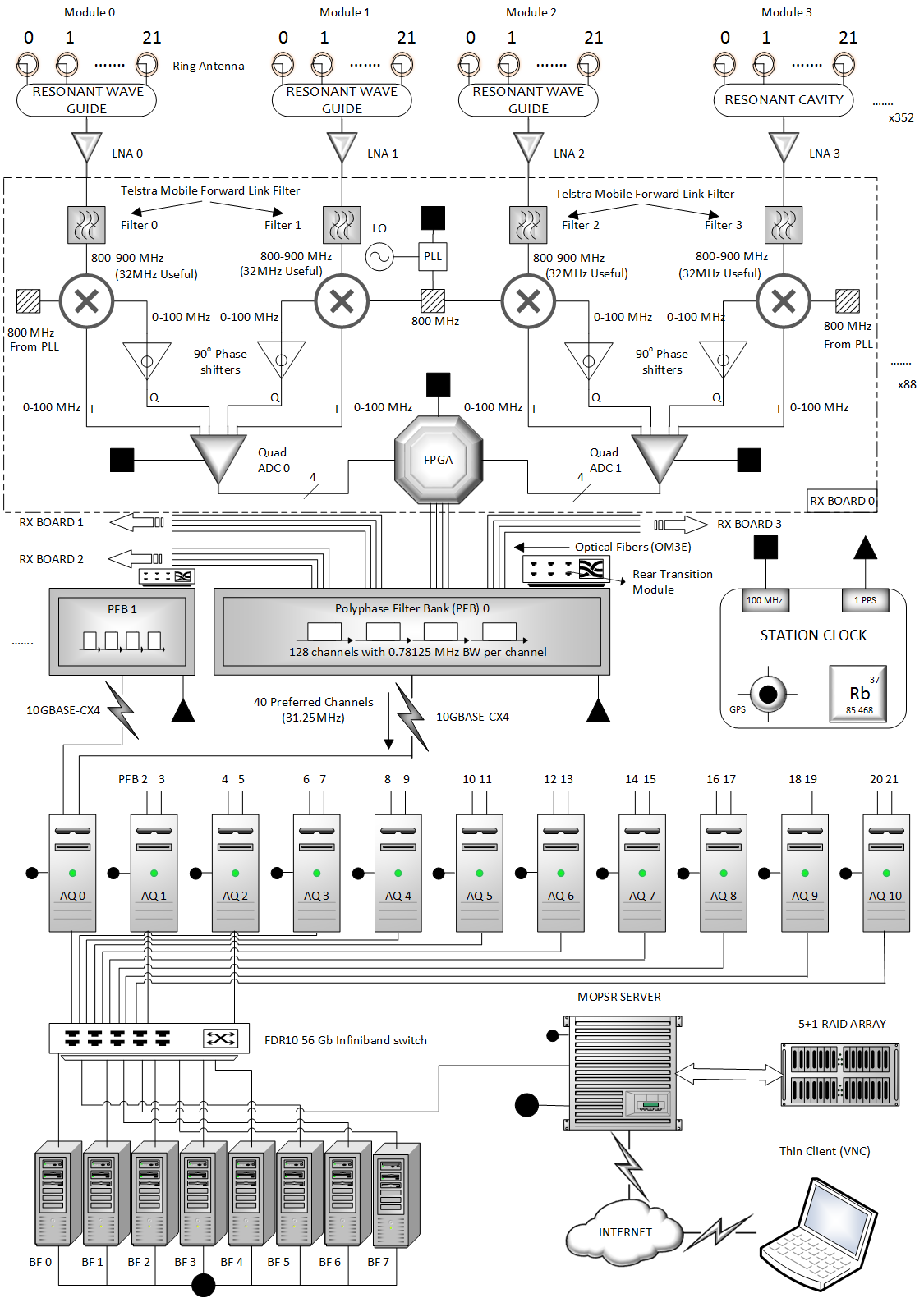
Image credit: Vivek V K.